A research-led interpretation of how material characterisation, transfer-matrix modelling and layer optimisation can deliver quieter, thinner and more predictable acoustic shielded enclosures.

Designing an enclosure that is both quiet and acoustically useful
Acoustic shielded enclosures carry a deceptively complex brief. Their walls must prevent external noise from contaminating a measurement or occupied space, while their internal surfaces must suppress reflections strongly enough to create a stable, predictable acoustic field. One task is governed mainly by sound transmission; the other by absorption. Treating them as separate problems often produces a heavy enclosure that still performs poorly at low frequency.
The study by Fang and colleagues offers a valuable route through this conflict. It combines measured porous-material properties, a Johnson-Champoux-Allard model, transfer-matrix analysis and micro-perforated panel tuning to improve both sound transmission loss and internal absorption. The central lesson is not that one material is universally superior. It is that acoustic performance emerges from the interaction between mass, damping, airflow resistance, cavity depth and layer sequence (Fang et al., 2026).
| Engineering answer in one paragraph Porous absorbers are highly effective when particle velocity is sufficient, but their performance weakens as wavelength increases. A micro-perforated panel adds a tunable resistive-reactive mechanism for low frequencies, while denser barrier layers and carefully arranged interfaces increase transmission loss. The research shows that the best enclosure is therefore a coupled system: the barrier controls what passes through, and the absorber controls what remains inside (Fang et al., 2026). |
Research results at a glance
| Barrier optimisation | Low-frequency absorption | Low-frequency insulation |
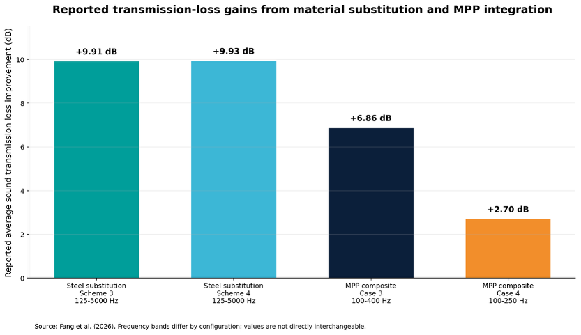
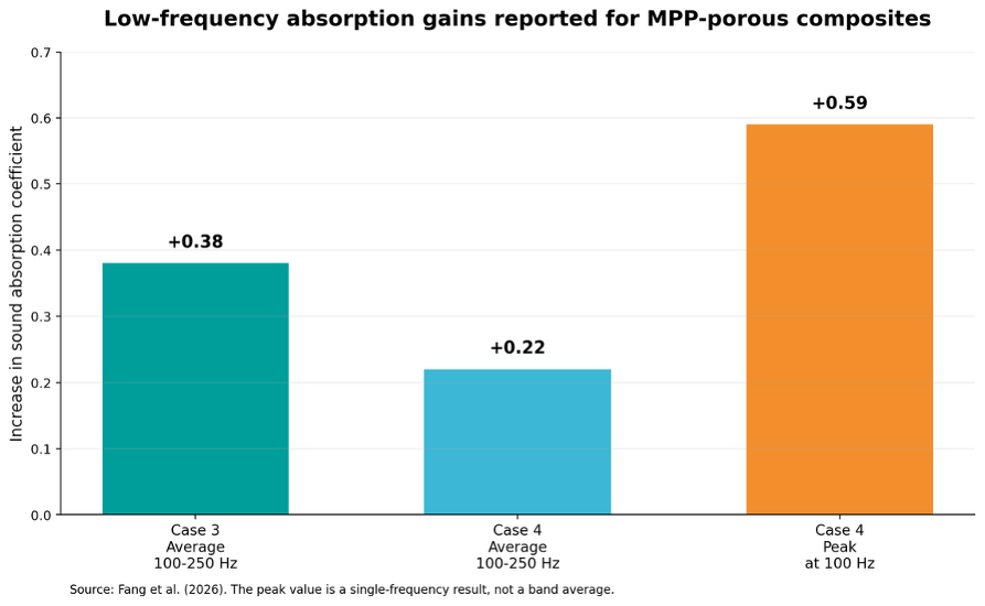
| +9.91 to +9.93 dB average STL across 125-5000 Hz after replacing 9 mm MDF with 2 mm steel; total build-up reduced by 6 mm. (Fang et al., 2026) | Average SAC increased by 0.38 for Case 3 and 0.22 for Case 4 across 100-250 Hz; Case 4 peaked at +0.59 at 100 Hz. (Fang et al., 2026) | MPP-integrated composites increased average STL by 6.86 dB across 100-400 Hz in Case 3 and 2.7 dB across 100-250 Hz in Case 4. (Fang et al., 2026) |
1. Why acoustic enclosure performance is a coupled problem
A conventional enclosure specification can encourage a material-by-material mindset: add steel for mass, damping compound for panel vibration, mineral fibre for absorption and an internal lining for finish. Yet these elements are acoustically coupled. Moving a layer changes the impedance discontinuities seen by the incident wave. Replacing a panel changes not only mass, but also bending stiffness, coincidence behaviour and the dynamic interaction with adjacent layers. Adding an absorber changes cavity losses and can alter the resonance that governs low-frequency behaviour.
This coupling is especially important below 250 Hz. At these wavelengths, practical porous linings are acoustically thin, and the pressure and velocity distributions within the wall cavity become decisive. Simply increasing fibre thickness can help, but space, weight, maintenance and fire-performance constraints often limit that route. A tuned micro-perforated panel can introduce additional viscous and thermal losses at the perforations, with the porous backing and cavity depth shaping the resonant response (Fang et al., 2026).
For HVAC plant enclosures, test cells and MEP service rooms, this is not an academic distinction. Low-frequency tonal energy from fans, compressors, pumps and rotating equipment is often the most difficult component to attenuate. The enclosure must therefore be engineered around the actual source spectrum, not a single overall sound level.
2. From measured porous media to a predictive model
Fang et al. measured glass-fibre-wool absorption using the transfer-function method in two impedance tubes. A 100 mm tube covered 160-1600 Hz, while a 29 mm tube covered 500-6400 Hz; specimens were tested at 25 mm and 50 mm thicknesses. The overlapping frequency range was used to reconcile the two data sets before inverse characterisation (Fang et al., 2026).
The researchers then identified the five parameters required by the Johnson-Champoux-Allard model: porosity, flow resistivity, tortuosity, viscous characteristic length and thermal characteristic length. This matters because bulk density and nominal thickness alone cannot describe the acoustic behaviour of fibrous media. Two products with similar density can exhibit very different resistance to oscillatory airflow, and therefore different absorption and transmission-loss behaviour.
Identified glass-fibre parameters used in the study
| Density kg/m³ | Porosity – | Flow resistivity N·s/m⁴ | Viscous length µm | Thermal length µm | Tortuosity – |
| 96.0 | 0.96 | 27,500 | 39.6 | 79.3 | 1.0 |
Table 1. JCA parameters inversely identified for the glass fibre wool. Source: Fang et al. (2026).
Validation was strongest for the 50 mm sample and for the 25 mm sample between 1000 and 2000 Hz. The authors reported larger deviations above 2000 Hz for the thinner specimen, which they attributed to experimental boundary effects (Fang et al., 2026). For engineering teams, this is a reminder that inverse parameters are only as reliable as specimen preparation, mounting, leakage control and the frequency range used for fitting.
Once the porous medium was characterised, the study cascaded the transfer matrices of each layer to calculate the acoustic response of the complete assembly. This offers a rapid way to compare material sequence, thickness and substitution before committing to prototypes. It is particularly useful for screening design options, provided that the final design is still checked against finite panel behaviour, joints, penetrations and site conditions.
3. Why micro-perforation changes the low-frequency response
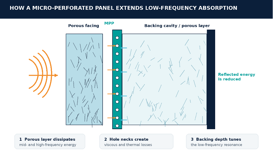
In the composite studied by Fang et al., sound first encounters the glass fibre wool. The porous medium dissipates part of the acoustic energy through viscous interaction with the fibre network. The remaining energy reaches the micro-perforated panel, where narrow apertures behave as resistive necks. Together with the backing volume formed by the porous layer and cavity, these apertures create a distributed resonant system analogous to many small Helmholtz resonators (Fang et al., 2026).
The key design variables are aperture diameter, perforation ratio, panel thickness and backing depth. In the study, the investigated MPP used 0.4 mm apertures and a 0.1% perforation ratio in a 2 mm panel configuration. Those values should not be copied indiscriminately. They were effective within the specific layer build-ups modelled, and the optimum will shift with target frequency, cavity depth, airflow resistivity and manufacturing tolerance (Fang et al., 2026).
| Practical design implication An MPP should be specified as a tuned acoustic component, not as a decorative perforated sheet. Hole diameter, open area, thickness, backing depth and the condition of the perforations after coating or installation all affect resistance and resonance. Even a well-modelled design can underperform if paint, adhesive, dust or a protective facing partially blocks the apertures. |
4. Re-engineering the wall build-up: sequence, mass and compactness
The baseline wall was a five-layer assembly comprising 50 mm glass fibre wool, 9 mm MDF, 25 mm glass fibre wool, an 8 mm viscoelastic damping layer and a 2 mm steel plate. The researchers compared this arrangement with three alternatives based on layer reordering and replacement of the MDF with steel (Fang et al., 2026).
Reordering the 25 mm glass fibre and damping layers produced a mixed result. Scheme 2 lost 5.41 dB at 100-125 Hz, where mass-law behaviour dominated, but gained an average 5.6 dB across 160-4000 Hz. The study attributed the broader improvement to stronger impedance contrast and wave reflection created by the revised sequence (Fang et al., 2026). This is a useful warning against judging a layer sequence from one frequency or one averaged number.
The more decisive change was replacing the 9 mm MDF with a 2 mm steel plate. Schemes 3 and 4 increased average sound transmission loss by 9.91 dB and 9.93 dB respectively over 125-5000 Hz, while reducing nominal build-up thickness by 6 mm. The 0.02 dB difference between the two stacking orders indicates that, for these particular alternatives, material substitution dominated the sequence effect (Fang et al., 2026).
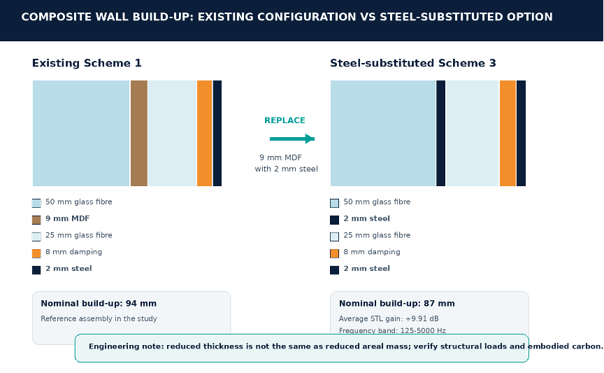
| A critical mass-versus-thickness distinction The thinner assembly should not automatically be described as lighter. The study attributes the transmission-loss gain to increased surface density, and 2 mm steel can carry more areal mass than 9 mm MDF. Structural support, handling, seismic restraint and embodied carbon therefore need separate verification. Compactness is a demonstrated benefit; weight reduction is not established by thickness alone. |
5. When absorption and insulation reinforce each other
The internal absorption analysis used the steel-substituted structure as a base and compared four configurations. Two cases used glass fibre alone, while two combined glass fibre with an MPP. Case 3 paired 25 mm glass fibre, an MPP and a further 25 mm glass-fibre layer. Case 4 paired 50 mm glass fibre, an MPP and a 25 mm backing layer (Fang et al., 2026).
Case 3 increased the average sound absorption coefficient by 0.38 across 100-250 Hz relative to its reference case. Case 4 increased the average by 0.22 over the same band and achieved a peak improvement of 0.59 at 100 Hz. Both configurations also improved absorption over the wider 100-630 Hz range, with the characteristic dip-then-rise shape associated with resonant interaction between the perforated panel and backing system (Fang et al., 2026).
When the MPP absorbers were returned to the complete wall model, Case 3 delivered a 6.86 dB average increase in sound transmission loss across 100-400 Hz, while Case 4 delivered 2.7 dB across 100-250 Hz. The authors linked the stronger Case 3 result to the greater porous thickness within the composite core, which increased impedance mismatch and widened the useful insulation band (Fang et al., 2026).
The broader engineering insight is that absorption and insulation need not be traded against each other. A porous-MPP system can reduce reflected energy inside the enclosure while also altering the impedance conditions that govern transmission. The value lies in tuning the complete stack so that the absorption peak, barrier response and source spectrum support one another.
6. What modelers and specifiers should not overlook
The study provides a strong optimisation framework, but real enclosures introduce mechanisms that a one-dimensional normal-incidence model cannot fully represent. The transfer-matrix method is most powerful as a design-screening and tuning tool. It should be complemented by prototype testing, finite-size analysis where necessary and site verification.
Finite panels, oblique incidence and room modes
Large enclosure panels bend, radiate and interact with their frames. Diffuse or oblique incidence can shift the apparent response from normal-incidence predictions. Inside the enclosure, low-frequency modes may create local pressure maxima and minima that obscure material performance. The design therefore needs spatial acoustic criteria, not only a single-point absorption target.
Doors, seals and service penetrations
A high-performing wall can be defeated by a door perimeter, cable transit, ventilation path or removable panel. Leakage paths are especially damaging at mid and high frequencies, while poorly isolated penetrations can create structure-borne short circuits. Every interface should be treated as part of the acoustic construction, with compression seals, labyrinths, flexible connectors and maintainable access designed from the outset.
Vibration control and panel mobility
Sound transmission loss is only one route. Fans, compressors and pumps can excite enclosure panels through mounts, pipes and ducts. Viscoelastic layers can reduce panel response, but the entire load path must be addressed through resilient isolation, flexible connections, adequate static deflection and avoidance of rigid bridging. In seismic regions, acoustic isolation and restraint must be engineered together rather than resolved in separate packages.
Manufacturing tolerance and durability
MPP performance depends on repeatable aperture geometry and open area. Coatings, corrosion protection, protective fabrics and cleaning regimes can change the effective resistance. Porous materials can also settle, compress or absorb moisture, altering flow resistivity and cavity depth. Specifications should therefore define tolerances, facing materials, assembly methods and inspection criteria, not only nominal acoustic ratings.
7. Sustainability: performance efficiency, not material minimalism
The reported 6 mm reduction in wall thickness demonstrates how modelling can recover valuable internal volume or reduce external footprint without sacrificing acoustic performance (Fang et al., 2026). In modular enclosures, plant rooms and constrained retrofit zones, that compactness can improve maintainability, coordination and transport efficiency.
However, a thinner wall is not automatically a lower-carbon wall. Substituting steel for MDF increases density and may increase embodied impact even where thickness falls. A credible sustainability assessment should therefore compare whole-life outcomes: material mass and recycled content, service life, replaceability, transport, structural support, fire strategy and the operational value of reliable acoustic control.
The most defensible environmental benefit is design precision. Better characterisation and modelling reduce the risk of overdesign, repeated site modifications and premature replacement. In acoustic test environments, improved low-frequency control can also shorten test time and increase data quality. In occupied buildings, predictable plant-noise control protects indoor environmental quality without relying on excessive operational restrictions.
| Sustainability question for every project Does the proposed assembly deliver the required acoustic outcome with the lowest whole-life burden – not merely the fewest millimetres? The answer should consider acoustic reliability, structural demand, durability, maintenance access and material circularity together. |
8. Where this design logic can add value
Although the paper focuses on acoustic shielded enclosures, the design logic is transferable wherever low-frequency absorption and high transmission loss must coexist. The details must be retuned for each application, but the underlying workflow remains consistent.
- Acoustic test chambers and product-development enclosures, where external isolation and internal field quality are equally critical.
- HVAC and MEP plant enclosures for fans, air-handling units, pumps, chillers and compressors with tonal low-frequency content.
- Generator, process-equipment and industrial machinery housings where airborne and structure-borne paths must be controlled together.
- Audiometric rooms, specialist studios and laboratory spaces requiring compact construction and predictable low-frequency behaviour.
- Rooftop and external plant screens where acoustic attenuation must be reconciled with airflow, weathering, access and structural loading.
For rooftop and ventilated systems, the lesson requires one further layer of engineering: noise control must not create unacceptable airflow resistance. Acoustic louvres, splitters, barriers and MPP concepts must be coordinated with pressure-drop limits, heat rejection, recirculation risk and fan operating point. True system performance is achieved when acoustic, mechanical and structural objectives are resolved in the same model.
9. A consultant-grade route from concept to commissioning
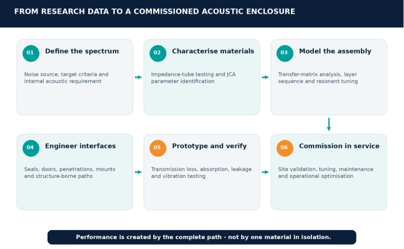
1. Define the acoustic duty
Set octave- or third-octave targets for external transmission, internal absorption and background noise. Identify tones, operating modes, duty cycle and the spatial locations that matter.
2. Characterise the real materials
Use validated flow resistivity or impedance-tube data for the actual porous product, density and compression condition. Avoid relying on generic catalogue descriptions when low-frequency performance is critical.
3. Optimise the complete assembly
Model barrier mass, damping, porous layers, cavities and MPP geometry as a system. Compare frequency-resolved performance rather than a single weighted rating.
4. Engineer every interface
Coordinate doors, vision panels, cable transits, ventilation paths, isolators, restraints and supporting steelwork. The weakest path sets the field result.
5. Prototype, measure and calibrate
Verify representative panels or a full mock-up. Use discrepancies to update material parameters, connection details and tolerances before production.
6. Commission under operating conditions
Measure the enclosure with the equipment running across relevant modes. Confirm airborne noise, vibration, leakage, internal field uniformity and maintainability, then tune where evidence shows it is necessary.
From Evidence to Engineering Practice
The research demonstrates that high-performance acoustic enclosures are not achieved by simply adding more fibre or more mass. Performance improves when measured material behaviour is converted into a predictive model, when the layer sequence is tested against the target spectrum, and when micro-perforated resonance is tuned to reinforce the porous absorber where it is weakest. The reported gains – more than 9.9 dB in broadband transmission loss for the steel-substituted schemes, meaningful low-frequency absorption increases, and up to 6.86 dB additional low-frequency STL for the MPP composite – show the value of treating the enclosure as an integrated acoustic system (Fang et al., 2026).
Kinetics Group applies this same evidence-to-implementation mindset across acoustic design, product engineering, manufacturing coordination, simulation, site installation and operational optimisation. The role of the engineering team is to bridge the gap between a promising laboratory configuration and a durable field solution – one that also satisfies airflow, vibration, seismic, access, fire and sustainability requirements.
For consultants, contractors and asset owners, the next step is to define the real spectrum and transmission paths before selecting the solution. Early technical coordination creates more freedom to tune the wall, cavity, perforation and interfaces; late acoustic correction usually adds cost, weight and complexity.
| Discuss an acoustic enclosure, HVAC noise-control or vibration-isolation challenge with Kinetics Group. Email: info@kineticsgroup.ae | sales@kineticsgroup.ae Telephone: +971 4 885 7361 Acoustic Enclosure: /https://kineticsgroup.ae/product/acoustic-enclosures/ |
Because true acoustic excellence is not achieved by adding mass blindly – it is achieved by engineering every transmission path.
Reference
Fang, K., Guo, Y., Fan, J., Wu, C. and Liu, T. (2026) ‘Application of acoustic perforated panels and porous materials in the design of acoustic shielded enclosures’, Journal of Physics: Conference Series, 3170, 012017. https://doi.org/10.1088/1742-6596/3170/1/012017
Editorial note: All technical visuals in this article are original explanatory graphics derived from the reported configurations and results. They are positioned beside the sections they are intended to clarify.