RIM Wood Floating Floor System

KINETICS® RIM Wood Floating Floor System is a lightweight, high-performance acoustic floating floor solution designed to reduce airborne noise and moderate impact vibration in dance studios, recording studios, music rooms, residential spaces, and mixed-use developments across the UAE, GCC, Middle East, and MENA region.

Product Details

Kinetics Noise Control Inc. Products

Product Description

High-Performance Wood Floating Floor System
KINETICS® RIM Wood Floating Floor System is an acoustic floating floor assembly designed for projects requiring strong noise and vibration isolation with a lower-profile, lightweight build-up. It is ideally suited for dance studios, loft-style condominiums, recording studios, music practice rooms, residential spaces, and other applications where airborne noise and moderate impact control are important.

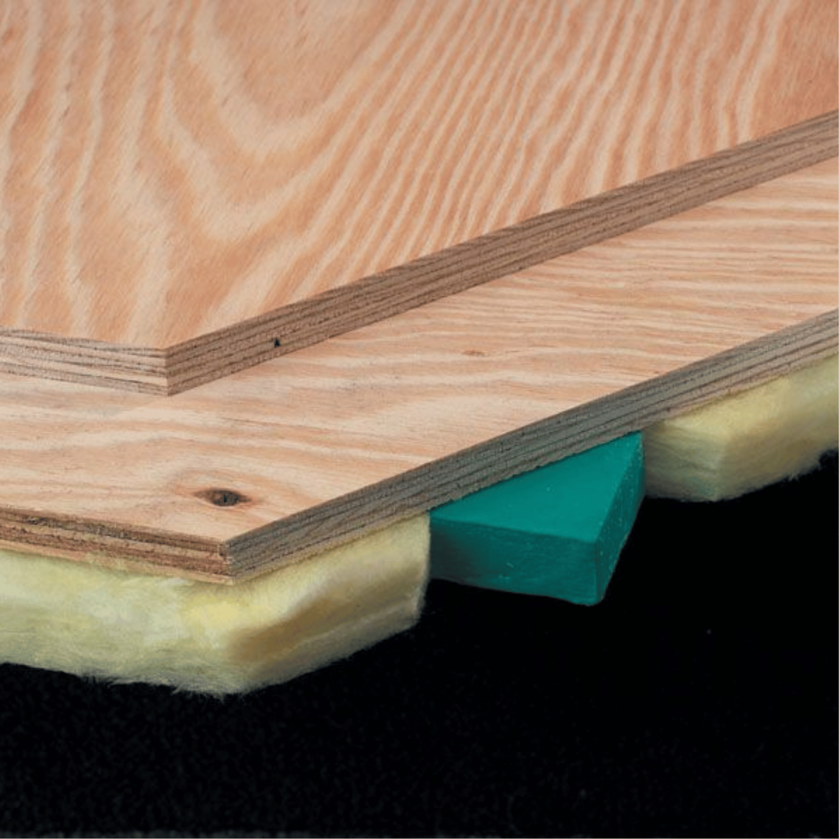
Rollout Isolation Material with True Airspace
The RIM Wood system uses rolls of acoustic batting to pre-space isolation pads, creating an airspace that is essential for effective floor noise control. Compared with continuous underlayments, a RIM wood floated floor can provide improved performance because of the airspace and lower natural frequency created by KIP pads spaced at 12″, 16″, or 24″ on center.

Designed for Load, Deflection, and Acoustic Requirements
RIM Wood can be supplied to fit different load conditions and can be designed for any load range. The system supports 1″, 2″, 3″, and 4″ airspaces, with optional channels or nailers available where additional stiffness or increased airspace is required. This allows acoustic consultants, architects, and contractors to coordinate the floating floor build-up with structural requirements, finished floor levels, and project-specific acoustic targets.

Practical Installation for Wood Floating Floors
Installation typically begins with a level subfloor, followed by a 3/8″ SRP perimeter isolation board adhered to non-isolated walls. The rolls of batting with secured pads are then rolled into place. Where heavy point loads exist, individual KIP pads are positioned according to project submittal drawings. Typical systems use two layers of 3/4″ plywood with staggered seams, while three layers of plywood may be glued and screwed together where added stiffness, mass, load distribution, and noise control are required.

Acoustic Flooring for Consultant-Led Building Projects
For UAE, GCC, Middle East, and MENA projects, KINETICS® RIM Wood Floating Floor System is suitable for buildings where noise control must be integrated with architectural floor levels, lightweight construction, and occupant comfort. It is especially useful for exposed-beam mixed-use buildings, studios, premium residences, entertainment spaces, and commercial interiors where impact sound and airborne noise must be reduced without using a heavy isolated concrete slab.

Important Design Note
For free-weight drops and fitness center applications, lightweight composite floors may be insufficient for high shock loads. Kinetics advises project teams to seek guidance when designing for these conditions, as impact loads may damage lightweight floor assemblies or isolators if the system is not correctly engineered.

Application

  • Dance studio acoustic floating floors
  • Recording studios and music practice rooms
  • Loft-style condominiums and residential spaces
  • Exposed-beam mixed-use developments
  • Home theaters, media rooms, and entertainment areas
  • Lightweight wood floating floor assemblies
  • Airborne noise and moderate impact vibration control
  • Residential, hospitality, education, and commercial acoustic flooring projects
  • UAE, GCC, Middle East, and MENA building acoustic applications

Features & Benefits

  • Lightweight wood floating floor system for acoustic isolation
  • Uses rollout isolation material with acoustic batting and pre-spaced pads
  • Creates true airspace, an essential component for floor noise control
  • KIP pads can be spaced at 12″, 16″, or 24″ on center
  • Can be designed for different load conditions and load ranges
  • Supports 1″, 2″, 3″, and 4″ airspace designs
  • Lower natural frequency helps improve isolation performance compared with continuous underlayments
  • Suitable for loud airborne noise and moderate impact applications
  • Allows variable isolator thicknesses and floor build-ups
  • Optional channels or nailers can increase stiffness and airspace
  • Fast, simple, and cost-effective installation approach
  • Typical build-up uses two layers of 3/4″ plywood with staggered seams
  • Three plywood layers may be used for added stiffness, mass, load distribution, and noise control
  • SRP perimeter isolation board helps reduce flanking vibration transfer
  • Individual KIP pads can be added for heavy point loads based on submittal drawings
  • Finished flooring can be installed according to the flooring manufacturer’s instructions
  • Helps improve acoustic comfort, privacy, and room usability
  • Supports acoustic consultant, architect, contractor, and developer coordination

Installation Guidelines

Installation of RIM System for a wood floated floor is similar to that of the isolated concrete slab. Starting with a level subfloor, a 3/8” thick strip of SRP (perimeter isolation board) is adhered to all non-isolated walls (the height of SRP is dictated by the height of the finished floor). The rolls of batting with secured pads are rolled out into place. If heavy point loads exist, individual KIP pads are then placed per submittal drawings. Typically, two layers of 3/4″ plywood are laid (seams staggered) over the isolation pads, and the finished floor is installed according to the manufacturer’s instructions. While two layers of 3/4″ plywood often proves suitable for most isolated wood floor composites, consider using three layers of plywood, glued and screwed together for added stiffness and mass, which aids in load distribution and noise control. Compare sound test AT001035 with AT001036 and discover how adding mass can boost STC results. The installation is completed by applying acoustical caulking to the top of the SRP board.

Installation Guidlines


Available Downloads Options

Datasheet
PDF
Installation Guide
Technical Manual
CAD
Drawings
Test
Reports
wpChatIcon
wpChatIcon

Send Us a Message