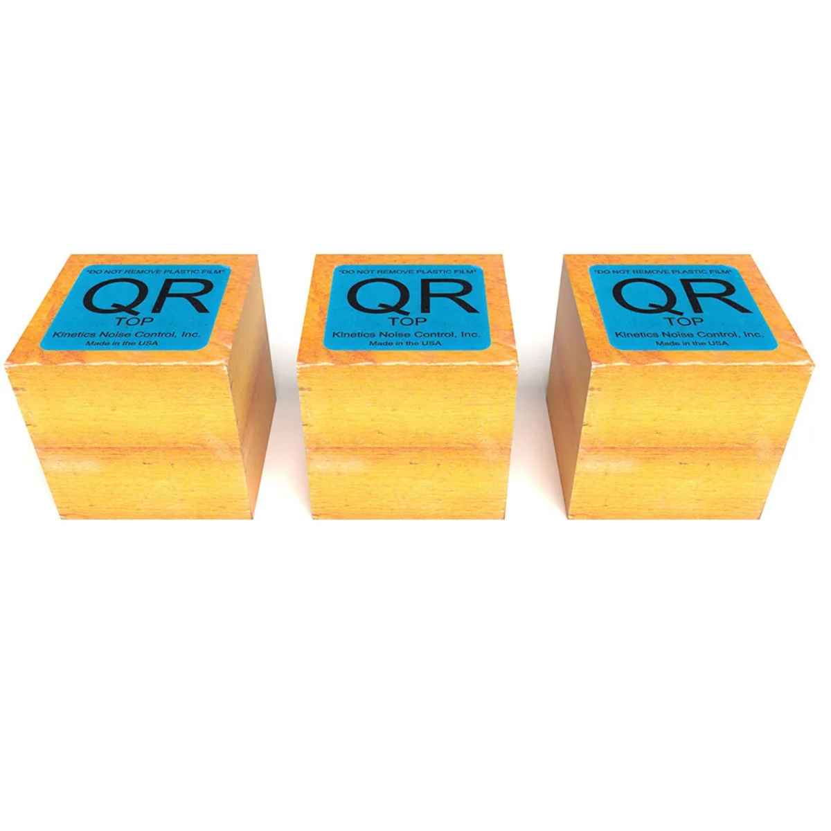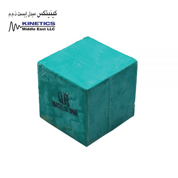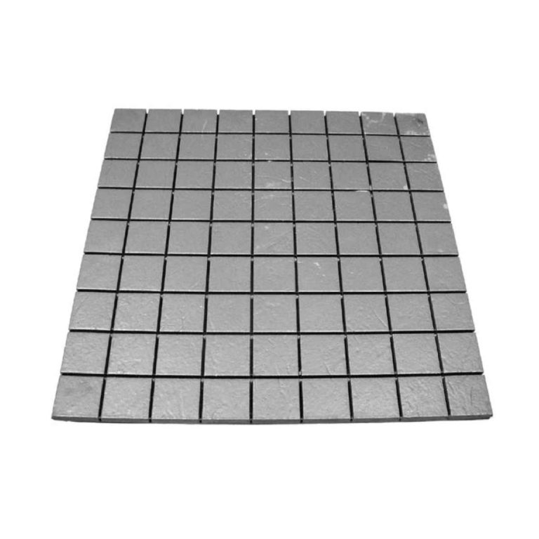
Kinetics Model KIP is a precompressed fiberglass vibration isolation pad for controlling noise, shock and vibration from HVAC equipment, industrial machinery and floating-floor systems. Its inorganic molded fiberglass matrix is enclosed in a flexible, moisture-impervious elastomeric membrane that allows controlled air movement and viscous damping. KIP pads support surface pressures from 5 to 500 PSI and maintain predictable dynamic behaviour across a wide load range. Kinetics Group provides product selection, technical submittals and project support across the UAE, GCC, Middle East and MENA region.
Engineered for Performance.
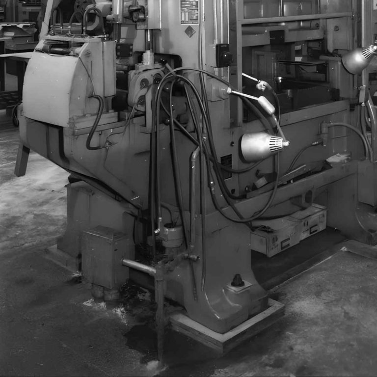
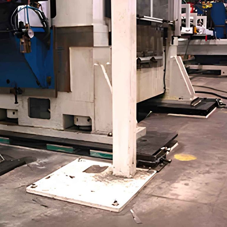
Kinetics Model KIP fiberglass vibration isolation pads are engineered for noise, shock and vibration control applications requiring predictable dynamic response and permanent load-support characteristics. KIP pads can be used beneath HVAC equipment, industrial machinery and acoustic floating-floor systems across the UAE, GCC, Middle East and wider MENA region.
Unlike a conventional solid rubber or neoprene pad, the KIP isolator consists of a high-density matrix of compressed molded inorganic fiberglass enclosed in a flexible, moisture-impervious elastomeric membrane. Controlled air movement between the fibers produces viscous damping, helping reduce motion caused by transient shock and vibration.
What Are KIP Fiberglass Vibration Isolation Pads?
KIP fiberglass isolation pads are resilient, load-bearing isolators designed to reduce the transfer of mechanical vibration, impact energy and structure-borne noise into the supporting building structure.
The fiberglass matrix acts as a system of bonded glass leaf springs. During manufacture, the fiber intersections are bonded with a water-resistant binder under controlled heat and pressure. The isolation material is then stabilised through ten precompression cycles at 300% of its maximum published load capacity.
This manufacturing process provides permanent resiliency, predictable performance and a 200% overload safety factor under the published operating conditions.
How KIP Fiberglass Pads Control Vibration
Mechanical equipment can transmit vibration through its base, support frame or inertia block into a slab, plinth or structural floor. KIP pads introduce a resilient separation between the equipment and supporting structure.
The flexible membrane permits controlled movement of air within the fiberglass media. The pumping action of air between the fibers creates viscous damping, which dissipates energy and reduces excessive movement caused by shock and vibration.
KIP fiberglass pads also maintain a relatively constant natural frequency across a wide loading range. This characteristic helps provide predictable dynamic performance where supported loads vary or where permanent load-support behaviour is important.
Load Capacity and Operating Range
| Technical Property | Published KIP Data |
|---|---|
| Surface-pressure range | 5 to 500 PSI |
| Metric surface-pressure range | 0.35 to 35 kg/cm² |
| Precompression process | Ten cycles at 300% of maximum published load |
| Published overload safety factor | 200% |
| Operating temperature range | -40°F to 250°F / -40°C to 121°C |
| Isolation media | Compressed molded inorganic fiberglass |
| External coating | Flexible moisture-impervious elastomeric membrane |
Important: The 5-to-500 PSI rating is a surface-pressure range, not the total load capacity of every pad. The permissible total load depends on the selected KIP density, pad dimensions, loaded surface area and project-specific support arrangement.
Technical Data and Product Selection
The information on this page is based on published Kinetics Model KIP technical literature. Final pad density, thickness, dimensions, quantity and spacing must be selected from the actual operating loads and approved project submittal. Contact Kinetics Group engineering support before procurement where equipment loads, impact conditions or support reactions are not confirmed.
How KIP Pad Thickness Affects Natural Frequency
The natural frequency of KIP fiberglass isolation media is primarily controlled by the isolator thickness rather than only by static deflection, as is commonly used for linear steel-spring selection.
For a KIP thickness other than 1 in. / 25 mm, the natural frequency can be related to the 1-inch value using the following manufacturer principle:
Natural frequency for the selected thickness = natural frequency of the 1-inch pad ÷ square root of the actual thickness in inches.
For example, a 4-inch / approximately 102 mm KIP isolator has approximately half the natural frequency of a 1-inch / 25 mm isolator of the same density operating at the same surface pressure.
Final density, thickness, pad area and natural-frequency selection must be confirmed from the applicable Kinetics selection data and approved project submittal.
KIP Pad Selection Requirements
The correct KIP pad cannot be selected only from the equipment name or total machine weight. Selection must account for the actual operating load at each support point.
The basic applied surface pressure is determined as follows:
Applied surface pressure = supported load at the pad ÷ loaded pad surface area.
Provide the following information to Kinetics Group for technical selection:
Technical selection notice: Do not determine KIP density, pad size, pad spacing or thickness from the published pressure range alone. Every selection must be checked against the actual supported load, required isolation performance and approved Kinetics technical data.
KIP Fiberglass Pads for Floating Floors
KIP pads can be incorporated into Kinetics RIM and FIC systems to resiliently separate an acoustic floating floor from the structural slab. The selected pad density and spacing are coordinated with the dead load, live load, required airspace, impact conditions and acoustic-performance criteria.
In a RIM system, KIP pads can be pre-spaced within fiberglass batting to simplify installation and maintain the designed layout. Additional individual pads may be required beneath concentrated or heavy point loads when identified in the project submittal.
Review the Kinetics RIM Floating Floor System and the Kinetics floating-floor system project article.
KIP Fiberglass Pads Versus Neoprene Pads
KIP and neoprene isolation pads should not be treated as interchangeable products. KIP uses a precompressed inorganic fiberglass matrix and is selected according to density, thickness, loaded area, natural frequency and surface pressure. Neoprene products use elastomeric material with different load-deflection and environmental characteristics.
KIP is particularly suitable where predictable dynamic response, controlled viscous damping and permanent resilient support are required. Where the required surface pressure exceeds the KIP load-carrying range, review the Kinetics NDM Flexco Isolation Pad.
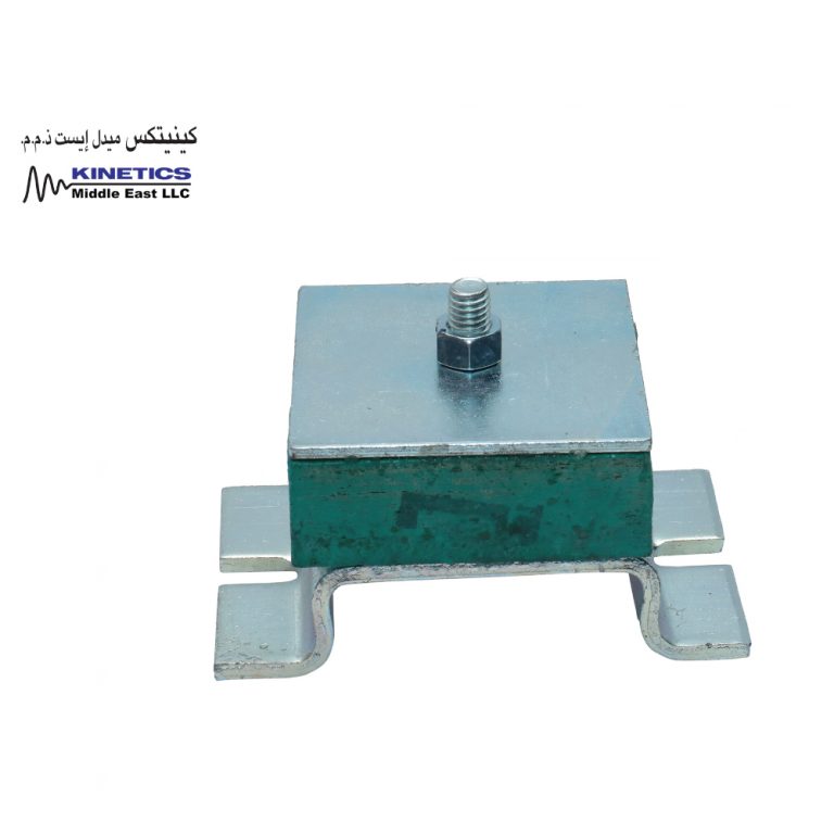
For a bolt-down fiberglass equipment mount, review the Kinetics AC Fiberglass Mount.
Technical Documentation
KIP Technical Support in the UAE and MENA
Kinetics Group supports acoustic consultants, MEP consultants, HVAC contractors, industrial engineers, machinery suppliers, developers and specialist contractors with KIP pad selection, technical submittals and project coordination.
Support is available for projects in Dubai, Abu Dhabi and throughout the UAE, as well as Saudi Arabia, Qatar, Oman, Kuwait, Bahrain, the wider Middle East, North Africa and MENA region.
Contact Kinetics Group for KIP fiberglass vibration isolation pad selection and project enquiries.
KIP pads are precompressed molded fiberglass isolators designed to reduce the transmission of noise, shock and vibration from mechanical equipment, industrial machinery and acoustic floating-floor systems.
KIP pads are available for published surface pressures from 5 to 500 PSI, equivalent to approximately 0.35 to 35 kg/cm². The total supported load depends on the selected density and loaded pad area.
Controlled movement of air between the bonded fiberglass fibers creates a pumping action that provides viscous damping and dissipates energy from transient shock and vibration.
Typical applications include high-speed fans, pumps and chillers installed on grade, particularly equipment operating at 1750 RPM and above when the selected pad configuration meets the project requirements.
Yes. KIP pads are used as resilient elements in Kinetics RIM and FIC floating-floor systems to improve the isolation of airborne sound, impact noise and structure-borne vibration.
Selection is based on the operating load at each support point, loaded pad area, required surface pressure, pad density, thickness, natural frequency, operating speed and installation arrangement.
The published isolation characteristics remain constant from -40°F to 250°F, equivalent to -40°C to 121°C.
No. KIP uses a precompressed inorganic fiberglass matrix enclosed in a flexible elastomeric membrane. Rubber and neoprene pads use different isolation media and must be selected from their own load and performance data.
Yes. For the same density and surface pressure, increasing the KIP thickness reduces its natural frequency. Final thickness must be selected using approved Kinetics technical data.
Send Kinetics Group the equipment operating weight, load at each support point, operating speed, pad dimensions, installation location and required isolation performance. Our technical team will assist with KIP density, thickness, pad area and layout selection for UAE, GCC and MENA projects.
KIP pad density, thickness, dimensions, quantity and placement must follow the approved Kinetics technical submittal.
Do not select or install KIP pads solely from the general 5-to-500 PSI range. Product density, thickness, pad area and spacing must be confirmed for the actual project load and required isolation performance.