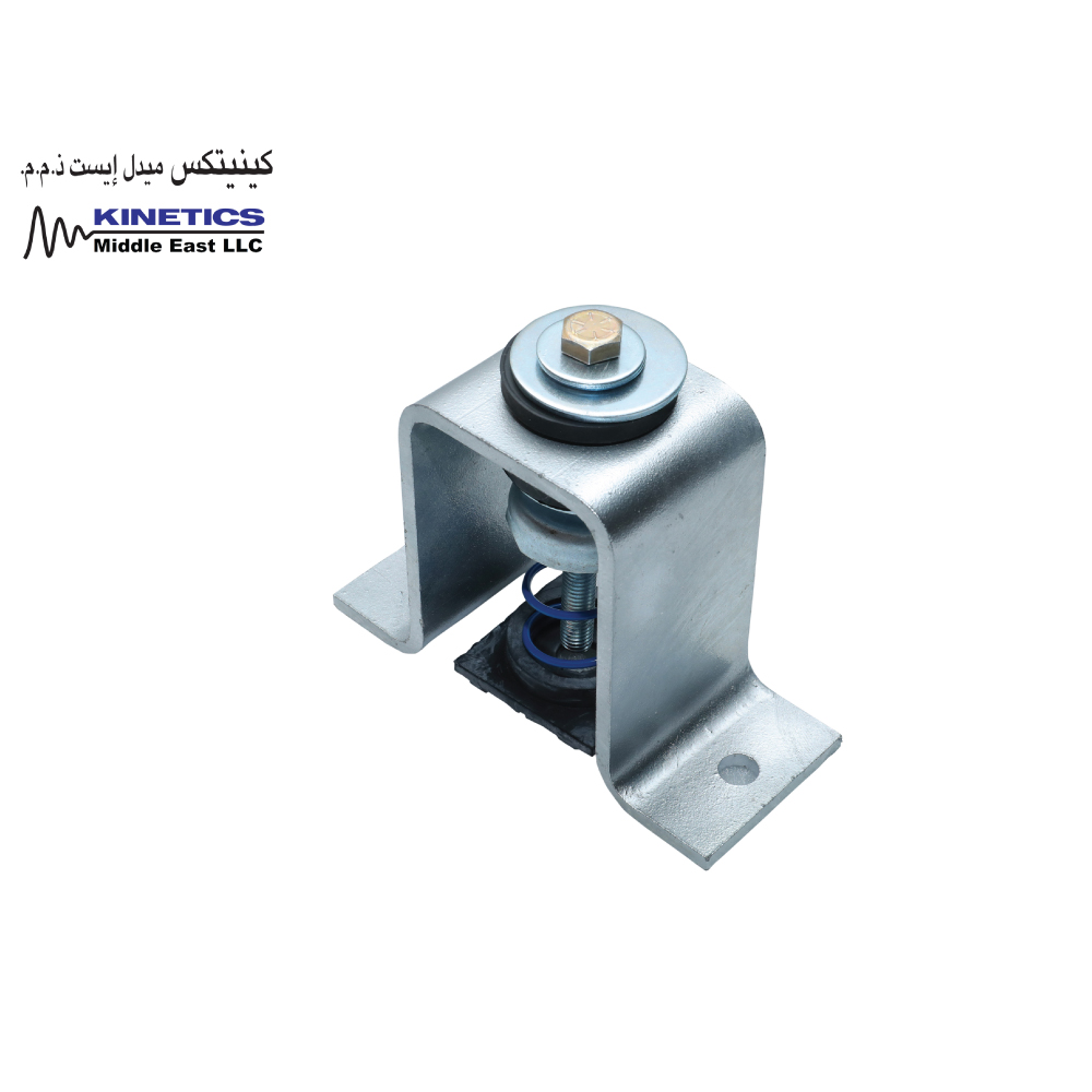
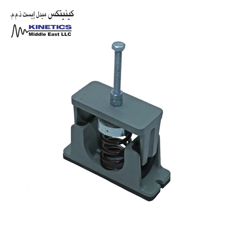
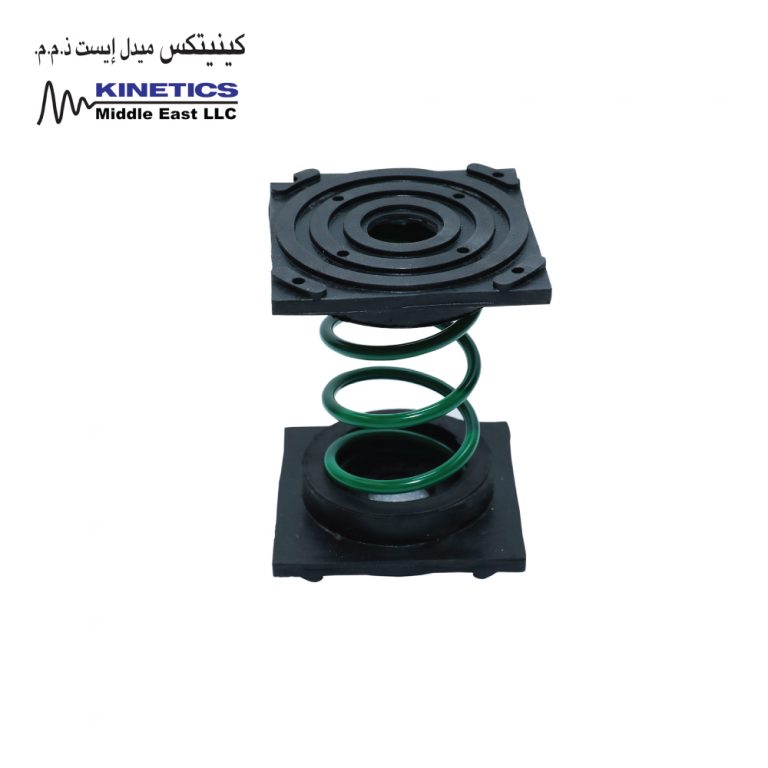
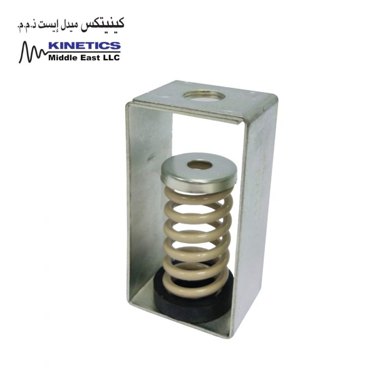
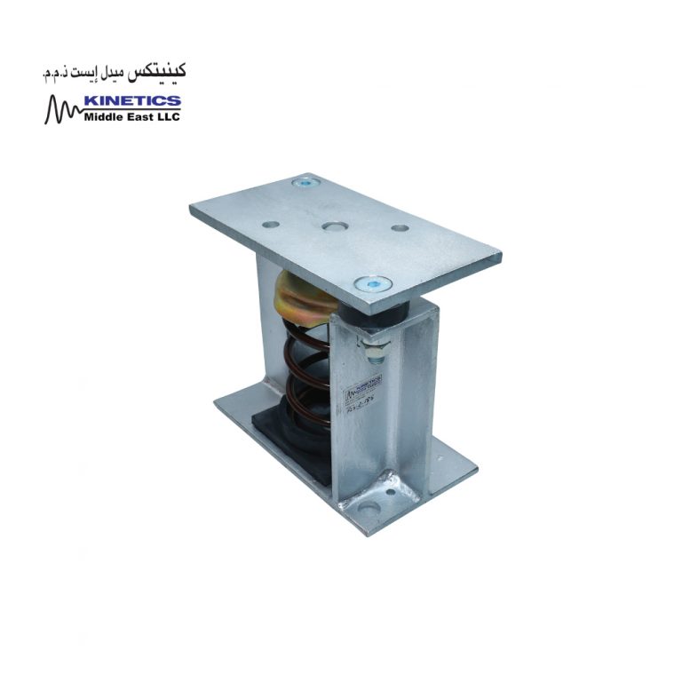
Model FHS Seismic Control Spring Isolators meet specifications for Kinetics Model FDS isolators and include a steel housing assembly to limit both lateral and vertical movement of the supported equipment during an earthquake without degrading the vibration isolation of the spring during normal equipment operating conditions.
Standard FHS isolators incorporate a steel housing which encloses a neoprene snubber. Depending on the load and seismic code, an optional steel load spreader plate may be applied to distribute the load among concrete anchors. A neoprene pad fitted in series with the spring is provided. Equipment attachment is by way of a bolt screwed downward through the equipment foot. Removal of the isolator for servicing can be easily accomplished as the isolator is not fitted with a protruding stud. In conformance with all current building code standards, the restraining system is designed to withstand a minimum 1.0 g acceleration force. Equipment motion is limited to approximately 0.2″ (5 mm) in any direction, at the isolator.
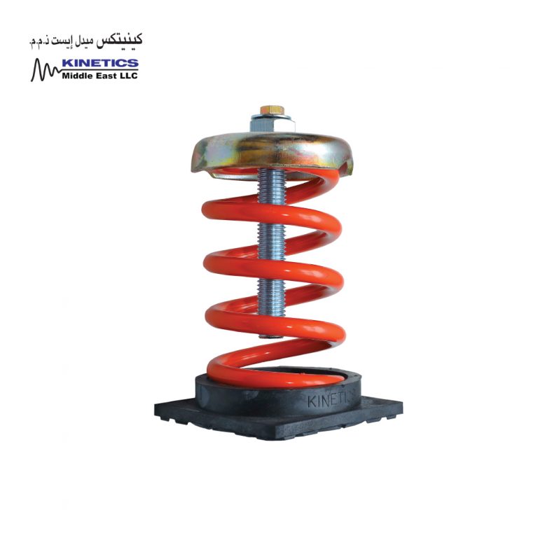
Spring isolators shall be seismic control restrained spring isolators, incorporating a single vibration isolator, having all the characteristics of Model FDS open spring isolators as previously specified. Springs shall be restrained using a housing engineered to limit both lateral and vertical movement of the supported equipment during an earthquake without degrading the vibration isolation of the spring during normal equipment operating conditions.
Vibration isolators shall incorporate a steel housing and snubbing grommet system designed to limit motion to approximately 0.2″ (5 mm) in any direction and to prevent any direct metal-to-metal contact between the supported member and the fixed housing. The restraining system shall be designed to withstand a force equivalent to 1.0 g in any lateral or vertical direction without yield or failure. Where the capacity of the anchorage hardware in concrete is inadequate for the required seismic loadings, an adapter plate to allow the addition of more or larger anchors will be fitted to fulfill these requirements. In addition to the primary isolation spring, the load path will include a minimum 0.25″ (6 mm) thick neoprene pad.
To facilitate servicing, the isolator will be designed in such a way that it can be removed without the requirement to lift or otherwise disturb the supported equipment.
Spring isolators shall be Model FHS as manufactured by Kinetics Noise Control.