Application
ASHRAE recommends that thrust restraints such as Kinetics Model HSR incorporate the same coil spring deflection as the support isolators. HSR Thrust Restraints are to be used for all fan heads, suspended fans, and all base-mounted and suspended air-handling equipment operating at 2 inches or greater total static pressure (TSP). HSR Thrust Restraints are always installed in pairs and often work in conjunction with inertia bases for floormounted fans to counteract fan thrust.
Total fan thrust can be calculated using the following formula:
| Thrust (lbs.) = | 0.036 x {TSP (in.)} x |
| {Fan Discharge Outlet Area (sq. in.)} |
To select the correct HSR Thrust Restraint to be used, this total calculated thrust is to be divided by two (2) and then rounded up to the next highest standard coil spring capacity.
Kinetics HSR Thrust Restraints are best utilized when located on the centerline of the discharge outlet of the fan. Fan instability can occur when attempts are made to control fan thrust only at the (floor-mounted) isolator locations. The attachment of the HSR brackets must be made at structurally sound locations and cannot be attached to bare unreinforced sheet metal ductwork.
The HSR coil spring is to be preloaded to allow for approximately 0.25″ (6 mm) of additional deflection due to fan motion upon start-up. HSR Thrust Restraint movement adjustment must be made under normal fan operational static pressures.

Description
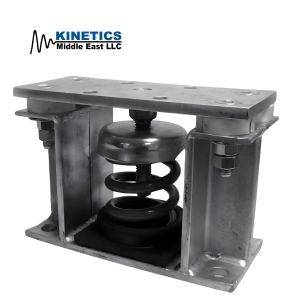
Kinetics Model HSR Thrust Restraints are used to counteract the discharge force created by fans during operation. HSR Thrust Restraints are used in pairs and best utilized when located on the centerline of the discharge outlet of the fan, bridging the flexible duct connector.
Kinetics Model HSR Thrust Restraints consist of high deflection, large diameter, laterally stable steel coil springs assembled into a threaded rod and bracket assembly. The coil springs have a lateral spring stiffness greater than 1.0 times the rated vertical stiffness to assure coil stability. The coil springs are designed to provide a minimum of 50% overload deflection capability to solid. The coil springs are polyester powder coated for corrosion protection, having passed a 1,000 hour salt spray test per ASTM Standard B-117. HSR Thrust Restraints feature molded neoprene end load plate assemblies for light capacities. For heavier capacities, Model HSR utilizes stamped steel end cups. HSR Thrust Restraints include threaded adjustment rod with hardware, fan and ductwork mounting bracket angles, bracket back-up plates, and all attachment hardware.
Specification
Thrust Restraints shall consist of high deflection, large diameter, laterally stable steel coil springs assembled into a threaded rod and angle bracket assembly. Coil springs shall have a lateral spring stiffness greater than 1.0 times the rated vertical stiffness to assure coil stability. Coil springs shall provide a minimum of 50% overload deflection capability to solid and shall be safe when temporarily loaded to solid capacity. Coil springs shall be polyester powder coated for corrosion protection and shall demonstrate successful completion of a 1000 hour salt spray test per ASTM Standard B-117. Thrust Restraints shall feature molded neoprene end load plate assemblies for light capacities or stamped steel end cups for heavier capacities. Thrust Restraints shall include threaded adjustment rod with zinc-plated hardware, and shall include primer painted fan and ductwork mounting bracket angles, bracket back-up plates, and complete fan / ductwork attachment hardware.
Thrust Restraints shall be Model HSR as manufactured by Kinetics Noise Control, Inc.


